
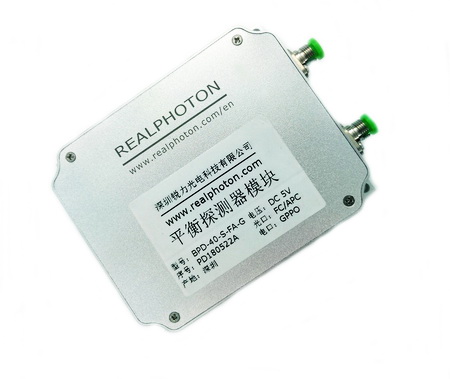

本平衡探测器模块内置一对镜像PD以及限幅型跨阻放大器, 具有高转换增益, 高带宽, 单端SMA(兼容2.92mm)输出, 支持最高速率可达40Gbps, 具有自动平衡补偿及眼图优化功能, 非常适合BPSK, DPSK和QPSK等应用.
DESCRIPTION
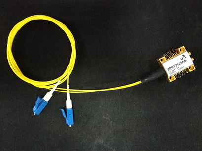
The balanced receiver module is ideally suited for a variety of applications up to 43 Gbps such as D/BPSK, D/QPSK and . The module consists of a pair of balanced photodiodes and a high-gain limiting transimpedance amplifier. The module has a typical conversion gain of 1000 V/W. Its dynamic signal integrity control allows excellent OSNR performance , which result in optimum eye pattern and the minimum bit errors ratio. The module is available with 2.92mm (SMA Compatible) RF outputs , AC or DC coupled versions.
FEATURES
Sensitivity, -10dBm typical, C&L Band
Typical 35GHz 3dB cut-off frequency
Output voltage Max. 280mVpp
Auto Optimum Signal Integrity Control
APPLICATIONS
43Gbps DPSK, QPSK Optical Transceiver
Radio Over Fiber, and Fiber Sensing
Testing and Measurement
SPECIFICATION
| Parameter | Unit | Min. | Typ. | Max. |
| Operating Wavelength | nm | 1200 | 1550 | 1650 |
| 3dB Bandwidth | GHz | 27 | 35 | – |
| Optical Input Power Range/Port | dBm | -10 | – | 4 |
| Conversion Gain | V/W | 800 | 1200 | 1400 |
| Maximum Output Voltage Swing | mVpp | – | 280 | – |
| DC output offset (for DC coupled version only) | mV | – | 200 | – |
| Photodiode DC Responsivity | A/W | 0.5 | 0.6 | 0.75 |
| Bit rate | Gbps | – | 43 | – |
| Skew | ps | – | 1 | 5 |
| Equivalent input noise density | pA/√Hz | – | 80 | 100 |
| Photodiode dark current/PD | nA | – | 5 | 50 |
| Signal Output and Couple | – | Single, DC or AC Coupled | ||
| RF Output Port | – | 2.92mm Female (SMA Compatible) | ||
| Optical Fiber and Connector | – | SM28-e, FC/APC | ||
| Adjustment Mode | – | Auto Optimum Signal Integrity Tuning | ||
| Operating Temperature | ℃ | 0 ~50 | ||
| Power supply* | – | DC 5V, 0.5A (Module) | ||
| Dimensions (L×W×H)* | mm | 100×80×20 (Module) |
Note: *The specifications subject to change without notice.
*The appearance and the key component varies according to different performance requirements.
ORDER INFORMATION
RX-BPD-1-2-3-4-5
| 1 | 2 | 3 | 4 | 5 |
| Package | Bandwidth | Wavelength | Electrical Interface | Connector |
| M=Module | 10=10GHz | C=C band | A=AC Coupled | FA=FC/APC |
| 35=35GHz | O=O band | D=DC Coupled |
EYE DIAGRAM NRZ at 20Gbps
