
BPRV2125A 双光纤尾纤输入,速率43Gbps, 可应用于DPSK系统; 射频接口GPPO, 差分输出; 差分转换增益2800V/W,3dB截止频率31GHz,输出电压摆幅600mV.
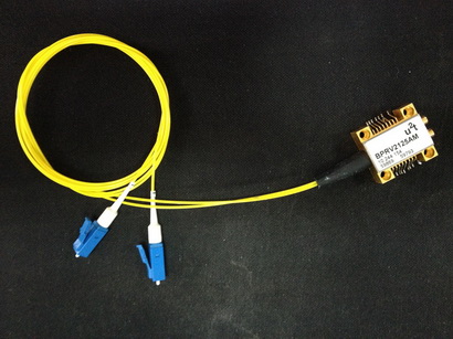
40Gbps DPSK Balanced Photo-receiver, U2T (Finisar) BPRV2125/ BPRV2125A, Fiber Coupled, Differential Output
The Balanced photo-receiver module BPRV2125A is a differential front-end for 43Gbits/s DPSK-applications featuring high differential gain. The photo-receiver module contains two waveguide-integrated PIN photodiode (PD) and a single chip and limiting amplifier (LA) within one small form factor SMD-package. The Receiver is therefore well suited for DPSK and DQPSK applications at 40G and 100G with rates between 20G and 56GBaud.
The DC output voltage can be monitored for OUTN and OUTP independently. For each amplifier path a threshold control at a linear amplification stage should be applied to ensure an optimized differential output signal.
An excellent electrical and optical phase propagation is achieved by a total skew of lower than 5ps between the balanced signal paths.
FEATURES
- Hermetically sealed SMD package with two GPPO connectors
- Balanced PIN / LA photo-receiver module
- 500mV differential output swing and very low skew.
- Wavelength range: 1530nm~1620nm
- Dual optical input, differential RF output with voltage swing of Max.600mW
- Typical 31GHz 3dB cut-off frequency
- Differential conversion gain 2800V/W @ 1550nm
- Sensitivity -10dBm@1550 nm
- Differential DC (BPRV2125) or AC (BPRV2125A) coupled output with threshold control option
APPLICATIONS
- 43 Gb/s DPSK communication systems
- Transponder and line card designs
- Radio over fiber
Optical Characteristics
| Parameter | Units | Min | Typ. | Max | Notes |
| Wavelength Range | nm | 1530 | 1620 | – | |
| Bit Rate | Gb/s | 43 | NRZ format | ||
| PD Responsivity | A/W | 0.50 | 0.60 | 0.75 | |
| Conversion Gain(differential) | V/W | 2000 | 2800 | – | |
| Equivalent Input Noise Density | pA/SqrtHz | 80 | |||
| Max. Operating Input | dBm | +4 | |||
| Sensitivity | dBm | -10 | |||
| Optical Input Return Loss(ORL) | dB | <-30 | -27 | ||
| Polarization Dependent Loss (PDL) | dB | 0.4 | 0.6 |
Electrical Characteristics
| Parameter | Units | Min | Typ. | Max | Motes |
| Signal Bandwidth | GHz | 27 | 31 | ||
| Electrical Return Loss | dB | -10 | 0.1-25GHz | ||
| Max. Output Swing | mV | – | 550 | 600 | @0dBm, Differential |
| AC Coupling Cutoff Frequency | KHz | 100 | |||
| Rise/Fall times | ps | 10 | 12 | ||
| Timing Skew | ps | 1 | 2 | ||
| Photodiode Dark Current | nA | <5 | 300 | At 25℃ | |
| Photodiode Bias Decoupling Capacitance | nF | 10 | Internal decoupling capacitance on each PD bias pins | ||
| Output Coupling | AC | DC is optional |
Note: * over operating case temperature specification;
Block Diagram